

This section continues our assessment of mechanical devices by looking at specific examples – including pulleys, gears, sheaves, and ramps. This will complete our understanding of the devices you need to know for this exam.
Posted in 2nd December, 2014 | Mechanical ComprehensionOther Simple Devices

Other Simple Devices

In this section, we will be looking at the following simple machines: pulley, sheaves, gears, and ramps. While this may seem daunting at first, it’s worth emphasizing the similarities and continuity that exists between these sections. In addition, we will also need to look at some form of calculation – most typically how to find the mechanical advantage of each device. This is similar to the method we used above, so all we need to do is understand the anatomy of each device and how it works with the concept of MA. The simple devices mentioned here will, of course, appear on your ASVAB Mechanical Comprehension exam, so revision here is essential to success in this regard.
Pulleys
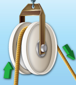
A pulley is a device used to hoist a heavy object. Also known as a block and tackle, the pulley typically operates by hoisting an object up through the use of a beam. This beam is additionally connected to a wiring system that connects both the object to be lifted as well as the method by which the pulley is “pulled”. Take a look at the diagram below as it illustrates this anatomy as well as reflecting on the terms you need to know to effectively calculate its mechanical advantage:

The distance between the fulcrum and the effort is known as the “effort distance”, while the distance between the fulcrum and the load is known as the “load distance”. Let’s not forget that MA is equal to effort distance divided by load distance – with this equation used to calculate simple pulley examples involving diagrams such as this.
Studying Mechanical Devices
Gears
What are gears? Put simply, they are simple devices used to increase the rate of force of movement. This is achieved through the use of objects with different numbers of teeth. There will usually be gears of different sizes, with the larger gear (driving gear) being responsible for the delivery of force. Let’s take a look at a simple example of what gears look like and how you can calculate the MA:
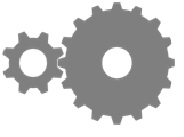
The left hand gear, we can see, has 8 teeth, while the larger gear has 16 teeth. This means the MA is 16/8, which is 2.
Sheaves
Sheaves are related to gears but differ by virtue of the fact the gears are connected by a series of belts. However, the calculation of MA is almost exactly the same. Take a look at the diagram below as it illustrates this process. Below, you will find how we can calculate the MA of a sheave system:
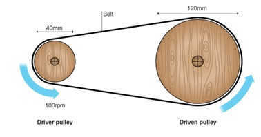
We can see two main components: the driven pulley and the driver pulley – both of which are connected by a belt. To calculate the MA of this system, we simply need to abide by the following equation:
- MA = (Driven Diameter)/(Driver Diameter)=120mm/40mm=3
Ramps
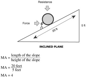
Also known as an inclined plane, ramps are often employed from a mechanical perspective to lift heavy weights from A to B. While it does not in and of itself employ a pulley-styled system, it still requires energy to make the transition from the bottom of the ramp to the top. For this reason, we can work out the mechanical advantage of a given ramp, as long as we know two details: the length of the slope, and the height of the slope. Via knowledge of these parameters, we simply need to divide one by the other to determine the mechanical advantage. Take a look at the illustration below for more details:
In the next section, we will take a look at the structure and properties of materials – an essential component of your ASVAB exam.
Share