

In this section, we take a look at the principles that underpin mechanical devices. These principles are essential to understanding mechanics and, as a result, frequently appear on the exam.
Posted in 2nd December, 2014 | Mechanical ComprehensionPrinciples of Mechanical Devices

Principles of Mechanical Devices


This section of our ASVAB Mechanical Comprehension study guide looks at what machines are and how they operate. Specifically, we need to know what we’re talking about before we will have any chance of describing it. A machine can be described as a tool which, through the use of force and movement, performs some intended action. A simple machine, such as a spanner, works by transferring the requisite amount of force to a bolt through the use of extended movements. Similarly, a more complex machine will have multiple parts moving in conjunction with one another, a standard example being that of a bicycle. In each of these instances, we see the transfer of energy taking place through processes that involve both force and movement.
The forces operating within a given system do so by a principle known as mechanical advantage (MA). In your ASVAB Mechanical Comprehension exam, you will be expected to calculate mechanical advantage from a standard set of conditions. As you progress throughout this section, we will come across such sample problems for you to practice, and the answers to these problems will also be provided. This should germinate the necessary foundation upon which you can complete questions not only in the self-assessment quiz at the conclusion of this section, but also during the examination process itself. Before we look at such examples, we need first to grasp some fundamental concepts of a standard machine.
Fundamentals of Simple Machines
We’ve already considered one example of a simple machine – the spanner – where a given force from our hand will supply and transfer the required energy to the bolt we wish to turn. Try not to think of machines as those requiring electrical connections as, in strictly scientific terms, a machine refers to the qualities of force and movement contained in a device as we described earlier. Moving on though and we can think of many other examples of simple machines, such as a wheel and axle, gear, pulley, lever, and screw. These simple devices work with the principles we have described thus far, but it’s worth exploring these devices in more detail to find out how they really operate in purely physical terms.

What is a lever?
A lever is a basic tool that helps you lift an object in some defined way. The diagram below illustrates this concept of a basic lever. Many machines utilize levers in their design as objects (or energy) need to be moved or distributed at certain times. There are three main “classes of lever” you will be expected to understand. Where these classes differ depends on where the forces are applied, and we’ll look at some practical examples of these classes in the section to follow. You will also be expected to understand how to calculate mechanical advantage which, if we correctly recall, refers to the force amplification achieved through use of a tool.
First, though, let’s take a look at each of these classes, with the upper example referring to Class I levers and the final example referring to Class III levers:
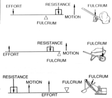
Notice each of these examples contains a fulcrum, but what is a fulcrum? A fulcrum is the location along the lever where the point of rotation takes place. In other words, the fulcrum is the point which will remain stationary while the lever rotates around this point. If we look at the examples above, this will make sense. In the middle example, that concerning the wheelbarrow, we can see where the fulcrum sits – and this point doesn’t move whether we lift the wheelbarrow up or not. The point of greatest resistance is located right next to the fulcrum, meaning less energy is required by the end user to lift the wheelbarrow, at least when compared to the first example.
The object to be lifted on a lever is referred to as its load. Returning to the second example, we see the load is located directly inside the wheelbarrow, next to the point of rotation of the fulcrum. In the first example, the fulcrum is located midway between the load and the load distance (the load distance referring to the length of the tool in question from the user to the load). The length of the handle, in the case of the wheelbarrow, is its load distance. The force required to lift the wheelbarrow is referred to as the effort, while the part of the lever from the fulcrum to the end user is known as the effort distance.

Although much of the terminology here may be new, always try to grasp the basics of the topic before coming back to “get” the full understanding at a later date.
With this in mind, we can now confidently return to the concept of mechanical advantage. We will go through three examples of such calculations, each one involving one of the classes of lever we outlined above. The first such example looks at a typical Class I lever.
To work this out, we need to know the formula to calculate MA, which is:
- MA = Load/Effort
Now, all we need to do is slot in our values to determine the effort required to lift the 200lbs of load in our Class I lever:
- 4 = 200lbs/Effort
We cannot work this problem out until what we’re looking for, “effort”, is isolated on one side of the bracket. Using simple algebraic rules, we can work the problem out as follows:
- (4)(Effort) = 200lbs
- Effort = 200lbs⁄4
- Effort = 50lbs
This is, as you can see, a relatively straightforward calculation. The algebraic rules applied here are the same as every other type – meaning you get to practice such rules for other ASVAB exams such as arithmetic reasoning and mathematics knowledge. You can identify a Class I lever as the fulcrum is found between the load (resistance) and the effort. In a Class II lever, though, the load is found between the fulcrum and the effort. Check back at the diagram above to discern these important distinctions. You may be asked to calculate the MA of a Class II lever and, in this case, we need recognize the different equation required in such an instance. The equation for Class II lever is as follows:
- MA = (Effort Distance)⁄(Load Distance)
The effort distance, if we recall from earlier, is the distance from the point of effort to the load, while the load distance is the distance from the fulcrum to the load. In our illustration above (the second example listed), the effort distance is 4ft while the load distance is 2ft – given that the load distance is always 50% of the effort distance as the fulcrum is located at the end of the lever. Therefore, by entering these values into the equation we find:
- MA = 4ft⁄(2ft ) = 2
We can now turn our attention safely to the Class III lever. In contrast to the previous two types of lever, the effort is between the load and the fulcrum. Return to our illustration above for further details. Some excellent examples of Class III levers include a pair of tweezers:
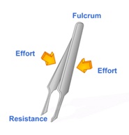
What is the mechanical advantage of this lever if the effort is 2lbs and the load (resistance) is 1lbs? To work this out, we need to return to the following equation:
- MA = Load/Effort
- MA = 2lbs/1lbs=0.5
When it comes to Class III levers, the MA will always be less than 1 – this is a useful point to keep in mind as it’ll help you verify whether or not you’ve attained a possible correct answer. When it comes to this example on tweezers, we can interpret what these values mean. It means that for every 2lbs of effort we apply to the tweezers, we achieve 1lb of “effort” on what we’re picking up. You might, alternatively, be asked to calculate the amount of force required to balance both sides of a lever. This type of question is usually followed by a diagram showing different weights on one side of the fulcrum, and asking you to calculate the weight required for the other side of the fulcrum in order to “balance” it out. Let’s take a quick look at one such example and reflect on a simple strategy you can employ to answer this correctly.
Take a look at the following diagram, illustrating a lever question where you’re asked to calculate the force, F, to balance both sides of the lever. We can see the fulcrum lying at the center, and two weights attached to one side of the lever. Let’s take a look at the best approach to solving this type of problem:
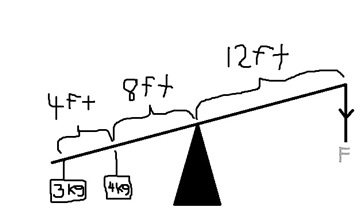
- (3kg x 12ft) .(4kg x 8ft) = (12ft x F)
- 36 .32 = 12F
- 68 = 12F
- 68/12 = F
- 5.6kg = F
Note what we did here. The calculation begins by equating both sides of the equation, with the left hand side of the equation equal to the right hand side. Note how the distance for each hanging weight is multiplied by its distance to the fulcrum – this is probably the most significant point you should bear in mind at this stage. When the equation is set up correctly, you simply need to apply basic algebraic rules by cleaning up both sides of the equation. At the end, you simply need to divide 68 by 12 to eliminate the 12 from the right-hand side of the equation and, in the process, have also successfully isolated F – the value we have been looking for.
The next section builds on the principles outlined here by focussing on other specific types of mechanical device.
Share